When sintered components show different dimensions, density
or surface condition depending on their position in the furnace, finding the cause
can be difficult. Temperature and pressure records may look consistent, yet the
finished parts reveal variation across the batch.
That variation can originate
in the powder, forming or binder removal stages. It can also reflect the way the
furnace delivers heat and distributes the atmosphere around the load. Before changing
the recipe, it helps to understand how those conditions are created.
The first article in this
series explained the vacuum sintering process and its place
in powder metallurgy.
We now turn to the equipment that makes
the process possible.
A stable vacuum sintering process requires a furnace architecture suited to the
material, thermal cycle and production load.
Hot-zone materials, heater placement,
gas paths, processing boxes and fixtures all contribute to the conditions the parts
experience.
Their value becomes clear when these choices are considered together.
Hot-Zone Materials: Graphite or All-Metal?
The hot zone is the heated, insulated assembly surrounding the working
space where the load is processed. Its construction influences heat losses, the
atmosphere and the maintenance needed to sustain performance.
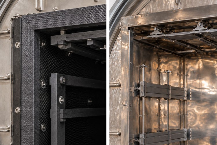
Graphite designs commonly use graphite heating elements with
graphite board or felt insulation.
All-metal designs use refractory
metal heating elements and multiple radiation shields, typically based on molybdenum
or tungsten according to the temperature and application.
The two arrangements manage heat losses through different mechanisms.
For sintering, the starting point is compatibility with the material and its
required chemistry.
Graphite can be appropriate for many applications, while
a process sensitive to carbon pickup may require an all-metal environment. The assessment
must include the trays and supports in contact with the parts, as well as the surrounding
hot zone.
Atmosphere requirements also matter.
Porous graphite insulation can retain moisture and gases that are subsequently
released during heating. This outgassing, or release of gas from furnace
materials, can affect evacuation and the process atmosphere.
An all-metal construction
reduces some of these sources, although cleanliness still depends on the load, fixtures
and condition of the complete furnace.
Energy demand should be compared over the intended cycle.
Heating the hot
zone and maintaining it at temperature are different demands; pressure and process
gas also influence heat transfer.
A configuration suited to short cycles may
offer a different balance during long holds.
Repairability and resistance to
repeated handling belong in the same evaluation.
Once the materials are compatible, the next question is how the hot zone delivers
heat to the load.
Hot-Zone Geometry and Heating Layout
Hot-zone geometry determines how the available space can be used and how heaters,
insulation and load supports fit around it.
A horizontal arrangement with a rectangular working space can
be convenient for stacked trays.
Cylindrical or vertical arrangements
may suit other load shapes, heating-element designs or temperature requirements.
The choice should follow the intended production configuration.
Under sufficiently low pressure, radiant heating is the main means of transferring
heat to the load.
Parts with a clear view of the heating elements receive radiation
directly; shielded parts receive more of their heat through surrounding surfaces
and neighboring components. This helps explain why the center of a dense stack can
heat differently from its exposed edges.
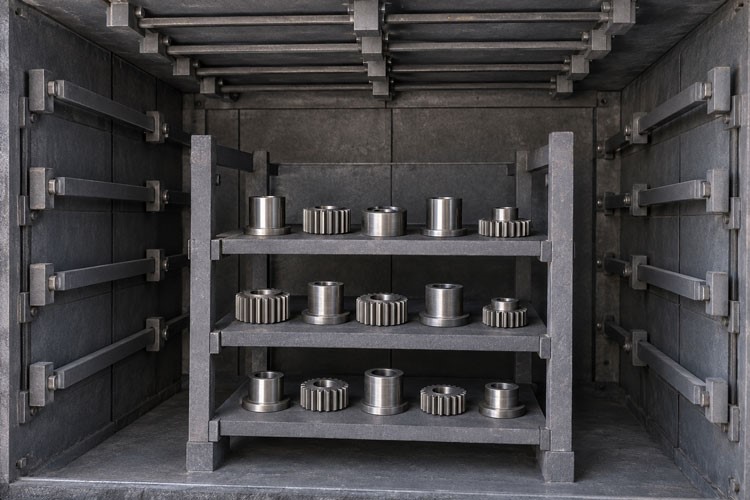
Heater placement and control zones therefore need to be considered alongside
the tray stack.
The arrangement should provide adequate heat input to
all relevant positions, including those near the door, load supports and other paths
through which heat can escape.
Additional control zones can help balance heating,
provided their sensors and control strategy are appropriate to the working space.
The distinction between heating and holding is particularly useful here.
A load may eventually reach an acceptable temperature distribution while still experiencing
substantial differences during the ramp. Those differences need to be assessed against
the material's process requirements.
Where gas-assisted heating
is available, its contribution must be evaluated under the actual pressure, gas
and circulation conditions.
The usable working space should consequently be defined by the load positions
in which the required conditions can be achieved. That gives production planners
a meaningful capacity figure and provides a basis for checking the heating layout.
Gas Flow Distribution Across the Load
When a cycle uses flowing process gas, the furnace must deliver that gas to the
regions where it is needed and provide a controlled route out.
Depending on
the processing stage, the flow helps maintain the required atmosphere and transport
substances released by the load.
Pressure, flow rate and distribution describe
different aspects of that behavior.
A pressure reading describes conditions
at the gauge connection. It does not establish how much fresh gas passes between
each pair of trays or what composition surrounds every part.
Gas flow through
openings and connections depends on their geometry and the pressure conditions across
them.
This makes the relationship between inlets, outlets and the load important.
Gas introduced close to an extraction point may have an easier path around the
stack than through it.
Closely spaced trays or densely packed components can
create regions with limited gas exchange.
Distribution manifolds, suitable openings
and defined flow passages can help guide the atmosphere through the intended working
space.
A useful design review asks:
- Where does the process gas enter relative to the occupied shelves?
- Which passages direct it through the load?
- Where could it bypass the parts or leave poorly supplied regions?
- How does the flow path change when the stack height or loading density changes?
These questions should be answered for the stages that use flowing gas.
The
required pressure, composition and flow can change during a cycle, so the same distribution
arrangement needs to be evaluated under each relevant operating condition.
This becomes especially important when the load sits inside a processing box.
Processing Box or Open Hot Zone?
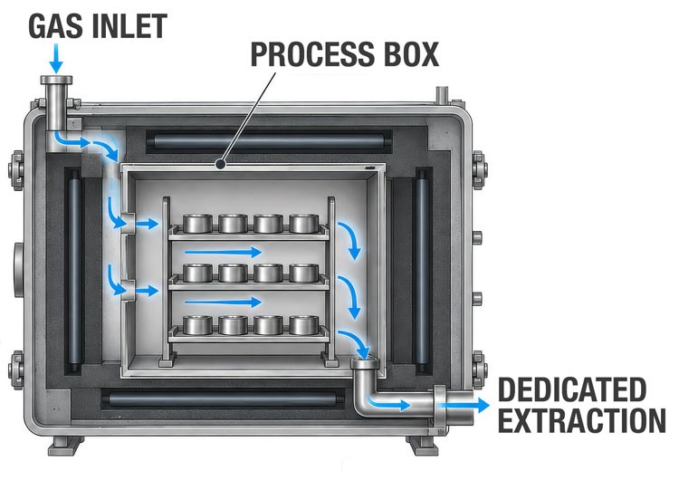
A processing box is an enclosure around the load, inside the hot zone,
that helps define the process-gas path and the atmosphere immediately surrounding
the parts.
Depending on its construction, it may also be described as a
retort.
Its connections and openings determine how it communicates with
the surrounding chamber.
In some combined debinding and sintering furnaces, gas enters
outside the box, passes into it and is extracted through a dedicated connection.
This arrangement can help carry binder by-products toward the removal system
while limiting their escape into the surrounding hot zone.
Other designs also
provide a direct gas supply to the enclosure for particular stages.
A controlled
pressure difference, with the box at a lower pressure than the surrounding chamber,
helps maintain inward gas flow and limit the escape of binder vapors.
The architectural purpose is to control where released substances travel.
Deposits left in the furnace can become a source of contamination during later
heating.
The box is one part of the strategy for managing this risk; its effectiveness
depends on the actual gas path, connections and operating conditions.
Binder chemistry and removal methods will be examined in the next article.
An open hot zone may be suitable where the incoming load and
process requirements allow it.
With the enclosure removed, more of the working
space can be available for parts, and the load can have more direct exposure to
the heaters.
Access for cooling gas may also improve, depending on the furnace design.

A box, meanwhile, adds material that must be heated and cooled
and can obstruct radiation or gas circulation.
These effects belong in the thermal
and capacity assessment.
The choice between a process box and an open hot
zone should be based on the box’s contribution to atmosphere control and the
thermal performance of the overall configuration with the intended load.
Load Arrangement, Trays and Part Supports
The furnace's heating and gas-distribution systems operate around whatever
production places inside them.
Trays, racks and supports are therefore part
of the process configuration.
Consider adding another shelf to an established stack.
It increases capacity,
but also changes the fixture mass, spacing and exposure of the parts below it.
Filling every tray more densely changes the available gas passages.
A loading
pattern that performed well in development needs to be checked again when these
features change.
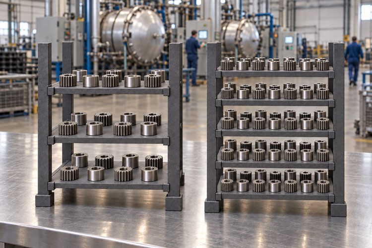
Tray material and thickness influence the amount of heat required and how the
parts are supported.
Flatness and condition matter too: a distorted tray can
alter both component positioning and the clearance between shelves.
Compatibility
must be assessed at the intended temperature and atmosphere, particularly where
parts contact the support surface.
Sintering introduces a further requirement because the component can shrink
and deform as its structure develops.
Setters, supports shaped
or selected to hold parts during sintering, help maintain the intended
geometry. Their contact surfaces must also accommodate the relevant shrinkage.
Friction or unsuitable constraints can resist local movement and contribute
to distortion.
The loading specification should record tray type, shelf spacing,
part orientation, support arrangement and permitted loading density. Operators then
have a defined configuration to reproduce, while engineers have a clear record for
investigating variation.
Upstream consistency remains part of that investigation.
Different green densities can produce different shrinkage behavior even when the
thermal conditions are controlled.
Comparing incoming parts alongside the loading
pattern helps determine whether a recurring dimensional problem begins in forming,
support contact or the furnace environment.
Fixed or Removable Box: Handling and Cooling
When the process calls for a box, its installation also needs to fit the production
workflow.
- A fixed box remains in the furnace while trays or an internal
rack are exchanged.
- A removable box travels with the load. Both arrangements
can be appropriate, depending on their interfaces and the cooling sequence.
A removable assembly allows the load to be prepared outside
the furnace and transferred as a unit.
Its practicality depends on consistent
positioning and reliable engagement with the required gas or extraction connections.
Each transfer should reproduce the intended flow path and support geometry without
disturbing fragile components.
A fixed enclosure can simplify permanent connections or mechanisms
that open the box during cooling.
The handling arrangement must then provide
access for trays or racks while protecting the box, heaters and insulation from
contact damage.
A fixed outer enclosure with a removable internal rack can offer
another option, with its own space and handling requirements.
Cooling deserves attention before the configuration is finalized.
A closed
box can restrict the cooling-gas path around the parts.
If the design opens
it or provides separate cooling passages, these features must work consistently
with the installed load.
Cooling rate should follow the material and dimensional
requirements, and its variation across the stack should be checked where relevant.
The handling choice can then be assessed through loading time, access, connection
reliability and cooling performance. These are practical features that help sustain
the qualified process in daily production.
Verifying Process Stability Under Production Conditions
Validation should connect furnace measurements with the results obtained from
parts in known load positions.
Three views of temperature are useful:
- the control sensor reading,
- the distribution within the working space and
- the thermal history of representative components.
A TUS (Temperature Uniformity Survey) measures temperature
variation at defined locations in the effective work zone. It provides evidence
about the furnace's thermal performance under the survey conditions.
Establishing
how production parts heat requires additional attention to their mass, shielding,
fixtures and measurement locations.
For process development or equipment acceptance, the trial should represent the
intended production configuration.
Include positions that are likely to be difficult
to heat or supply with gas, as well as accessible positions near the outside of
the load.
Where suitable, calibrated load thermocouples can
help establish heating delays and guide the definition of the sintering hold. Their
placement and use need to be appropriate to the temperature, material and applicable
process requirements.
The evidence should bring together:
- Temperature measurements through the relevant heating, holding and cooling
stages.
- Pressure, gas composition settings and recorded flow rates, with the measurement
locations identified.
- A load map linking trays, fixtures and component positions to the recorded
cycle.
- Part results by position, including the required dimensions, density or
porosity, surface condition and any relevant material tests.
Pressure and flow records alone cannot establish local gas composition.
Where atmosphere-sensitive results remain inconsistent, further investigation
may require suitable sampling or gas analysis.
Modeling can also help identify
likely flow restrictions, but its conclusions should be checked against measurements
and part results.
Repeated cycles then show whether the arrangement remains stable between batches.
Changes in stack height, fixture design or loading density should be reviewed
against the qualified configuration. If parts from a particular load position consistently
differ from the rest of the batch, investigate heat access, gas supply and support
conditions at that location.
Incoming-part variation should be assessed alongside
them.
Conclusion
A useful furnace specification brings material requirements,
thermal history, atmosphere conditions and loading practice into one coherent design.
It defines the usable working space, the intended configuration of the load and
the evidence needed to accept the resulting parts.
That makes comparison between furnace proposals more meaningful.
Each design can be evaluated against the same production task, including the
handling, cooling and maintenance needed to sustain it.
The resulting specification
also gives an existing installation a clearer basis for improvement.
Gaeda can support this evaluation
from an independent technical perspective, helping connect furnace requirements
with the material, production goals and long-term operating needs.
The next article will examine a critical stage within that environment: debinding,
and how to control binder removal and contamination before the final sintering conditions
are reached.
Download the FREE eBook

Choosing a vacuum furnace shouldn't rely solely on supplier brochures.
The Independent Vacuum
Furnace Buyer's Guide explains the technologies, components and design choices
that influence furnace performance, reliability and lifecycle costs.
It
gives engineers, production managers and technical buyers the knowledge needed
to evaluate solutions objectively and reduce investment risk.