A component can enter the sintering stage with its shape intact and still carry
a problem from binder removal.
Residual organic material may affect its chemistry,
while deposits left elsewhere in the furnace can release contaminants as the temperature
rises.
Debinding in vacuum sintering must therefore control
both the rate at which material leaves the part and its route out of the furnace.
The aim is to preserve the component while preparing a suitable environment for
the next stage.
The first article in this series
introduced the process;
the second examined furnace
architecture.
Here, we follow the binder from the incoming load to the collection
or exhaust-treatment system.
Along the way, we will examine a less obvious problem:
a condenser can collect binder products successfully and still become a restriction
in the extraction path.
Start with the Binder
System and the Incoming Part
A binder gives powder-based parts the cohesion and forming behavior needed before
sintering.
In MIM (Metal Injection Molding) and other
binder-based routes, it can contain several constituents with different removal
mechanisms.
A primary constituent may be extracted first, opening passages through
which the remaining material can escape.
A backbone binder, the constituent
that retains strength after primary removal, may then require thermal debinding.
This makes the condition of the incoming part essential.
A green component
containing its full binder system presents a different task from one that has already
undergone solvent, water-based or catalytic debinding.
A catalytic process for
a suitable polyacetal binder, for example, has its own chemistry and exhaust requirements.
Thermal removal can involve evaporation and decomposition, producing
substances different from the original binder.
The starting formulation
alone therefore cannot define what the condenser will collect.
Before developing the cycle, establish:
- The binder formulation and the amount remaining after any earlier treatment.
- The temperature ranges and rates at which its constituents are released.
- The component geometry, wall thickness and available escape paths.
- The acceptable residual chemistry before sintering.
Feedstock supplier information provides the starting point.
Thermogravimetric
analysis (TGA), which measures mass change during a controlled thermal program,
can help identify removal stages. Measurements at different heating rates support
cycle development, but results from a small laboratory sample need to be checked
against the behavior of the production load.
Integrated or Separate Debinding?
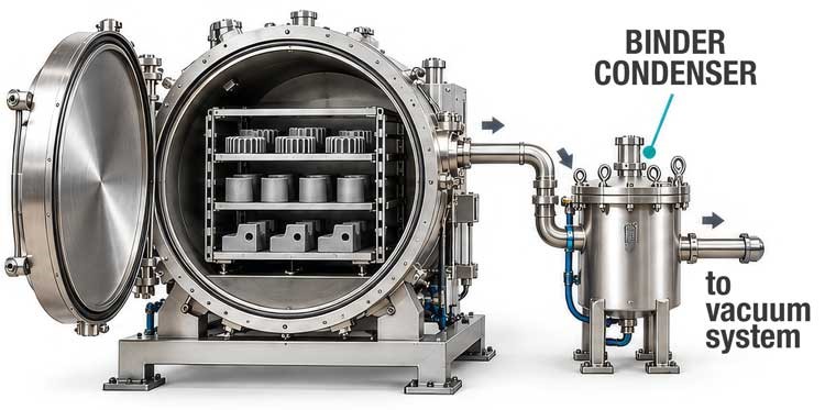
Combining thermal debinding and sintering in one furnace avoids
transferring parts when their strength may be low. It also avoids an intermediate
cooling and reheating sequence.
The equipment must, however, accommodate the released
binder products and establish the conditions required for subsequent sintering.
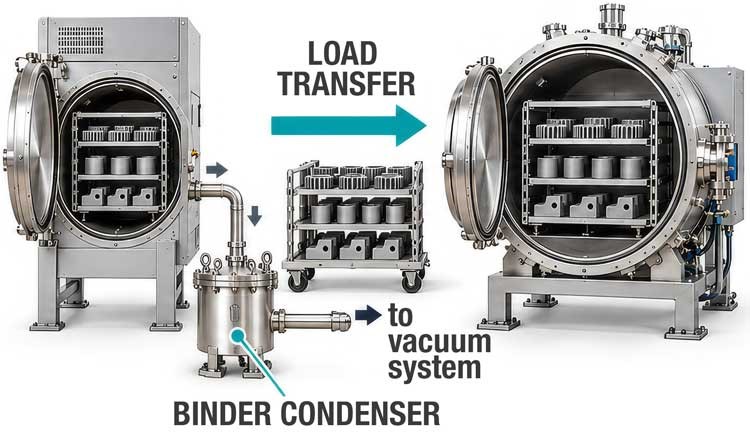
Separate equipment allows each stage to be matched to its task.
It can keep much
of the binder load away from the sintering hot zone and allow debinding and sintering
batches to run in parallel.
Handling becomes more demanding: debound parts may need
suitable trays, careful transfer or a compatible pre-sintering stage to develop
enough strength.
The comparison should use the actual production sequence.
A combined furnace
may still receive parts that have undergone primary debinding elsewhere.
Equally,
separate debinding does not guarantee that no organic material will enter the sintering
furnace.
Capacity depends on the duration of each stage, usable load size, transfers and
cleaning downtime. Energy demand also includes the hot zone, fixtures, atmosphere
and thermal losses.
These factors should be evaluated over representative cycles
before assuming that either arrangement offers better throughput or lower operating
cost.
Match Heating to the Rate of
Binder Release
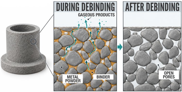
During thermal debinding, released gases must leave the component through its
available pore network.
If generation becomes too rapid for those escape paths,
internal pressure can damage the structure. Softening of the remaining binder can
also make the component vulnerable to distortion.
The heating program should follow the removal behavior of the binder system.
Controlled ramps and holds through critical release stages allow material to leave
progressively. A longer hold at the end cannot reliably repair cracking or distortion
created earlier.
The exhaust system experiences the same event at batch scale.
Two loads with
similar total binder content can impose different demands if one releases most of
it over a shorter interval. Peak release rate matters alongside total binder
mass.
This links the recipe to production loading.
More parts, thicker sections or
a different tray arrangement may change both heating behavior and the release profile.
A cycle demonstrated on a small trial should be checked again with the intended
production configuration.
The same release peak becomes important again at the exhaust-treatment
stage, where equipment must accommodate the highest demand within the cycle.
Control Pressure, Gas
Composition and Flow Together
A vacuum sintering furnace may perform debinding under reduced pressure
with a controlled process-gas flow.
The appropriate conditions depend on the binder,
powder and required chemistry.
The lowest attainable chamber pressure is not a universal
debinding target.
It is useful to distinguish two meanings often grouped under "partial-pressure
operation".
Furnace suppliers may use the term for processing below atmospheric
pressure with gas admitted.
In gas-mixture terminology, a partial pressure
is the contribution of an individual species to the total pressure.
A chamber-pressure
reading alone does not identify the concentration of binder-derived vapors.
Gas admission, extraction and the available passages influence how effectively
released substances are carried away.
The second article discussed
why gas can bypass
a dense tray stack. During debinding, such a path may leave some regions with limited
exchange even while the pressure controller maintains its setpoint.
Gas selection also requires material compatibility.
An inert atmosphere and a
reducing atmosphere serve different purposes; nitrogen, argon and hydrogen cannot
be substituted solely on cost or availability.
Hydrogen-containing processes require
equipment and operating sequences designed for that service.
The recipe should specify pressure, gas composition and flow for each relevant
stage, including the transition to sintering. These settings need to work with the
loaded furnace and its extraction system.
Keep Released Binder Away from
the Hot Zone
The route taken by binder products determines where contamination can develop.
Vapors can condense on cooler surfaces, while decomposition can leave deposits that
behave differently during later heating.
Material collected unintentionally inside
the furnace may become a source of contamination for the same load or subsequent
batches.
A processing box or retort can help define a dedicated extraction
route.
In designs that admit gas outside the enclosure and extract from within it,
an inward flow helps limit the escape of binder products into the surrounding hot
zone. This depends on the openings, connections and maintained pressure conditions.
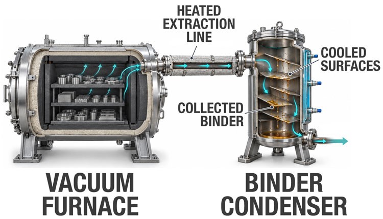
The extraction path then needs deliberate thermal management.
Heated outlet arrangements
can reduce premature condensation before the intended collection point.
Unheated
valves, connections or local cold spots deserve attention because deposits there
can restrict flow.
Line temperatures should suit the actual products being transported.
Simply increasing
the temperature without considering their decomposition behavior can create another
deposition mechanism.
The position of the treatment unit also matters.
As the next section explains,
treating the exhaust downstream of the vacuum pump does not protect the pump from
the vapors it has already handled.
Capturing Vapors and Treating
Exhaust Gases
Once released from the component, binder-derived products must be
carried out of the furnace and managed along the exhaust path.
The system may include a condenser, a thermal
oxidation unit, or both.
The two devices do not always need to be
present together: the configuration depends on the substances released and the
process conditions.
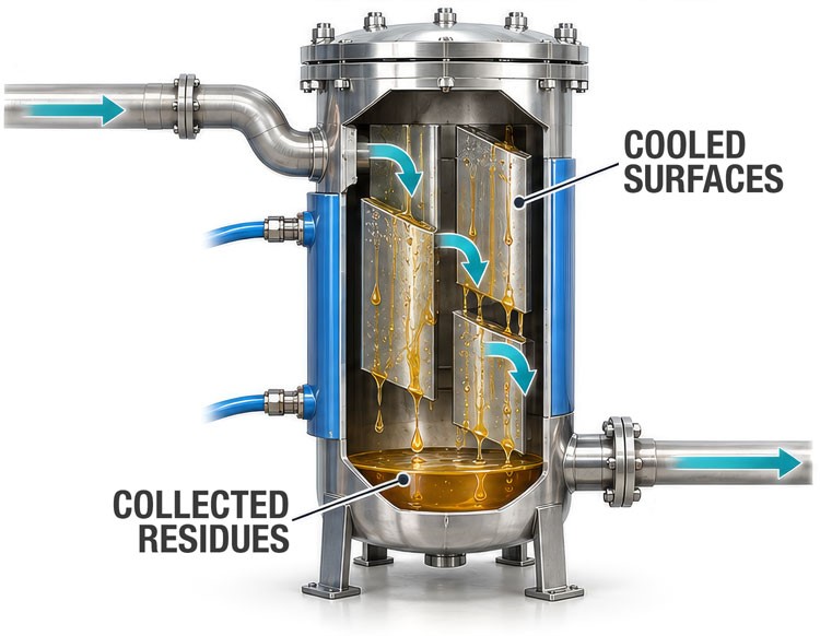
The condenser collects the
fraction that condenses on its cooled surfaces, forming residues that must be
drained or removed during cleaning. Substances that are not captured continue
along the line and require appropriate downstream management.
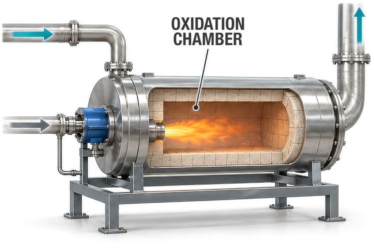
The thermal oxidation unit,
or afterburner, treats the combustible constituents of the effluent through a
controlled reaction with oxygen. Its function is to transform them chemically.
These two functions can therefore be used separately or combined.
However, exhaust treatment must be distinguished from vacuum pump protection: an
afterburner installed downstream of the pump does not prevent vapours from
passing through it. In this configuration, managing the condensable load may
require a condenser or other suitable separators upstream of the pump.
Where debinding operates with sufficient positive pressure to drive the exhaust
directly to a treatment unit, a route without vacuum pumping may be possible.
Transfer lines must still prevent unwanted deposits before the gas reaches that unit.
Capture and oxidation can also be combined within an exhaust-treatment arrangement.
The choice should follow the released substances, pressure conditions, gas flow
and peak organic loading.
A visible flame at a hydrogen exhaust does not establish that all binder-derived
compounds receive adequate treatment.
An oxidation system needs appropriate mixing,
temperature and residence time for its design duty.
Its capacity must accommodate
the expected release profile.
Condensation creates a collected waste stream; oxidation changes the exhaust
composition and requires its own utilities and operating controls. Both need to
fit the site's residue-handling and discharge arrangements.
Design the Condenser Around
the Actual Residues
Condenser design begins with the substances reaching it, their physical behavior
and the quantity released between cleaning operations. Its duty includes heat removal,
deposit storage and maintaining a usable gas path as material accumulates.
A large cooled surface is useful only if the vapor reaches it and the deposited
material can be managed.
Collection temperature, flow geometry and access therefore
belong in the same specification. The assessment should cover the operating condition
near the end of the intended service interval, as well as a clean condenser.
Liquid Residues: Provide
a Complete Drainage Path
When collected material remains liquid at the collection and discharge temperatures,
cooled surfaces can drain towards a receiver. Slopes, outlet positions and the absence
of pockets help prevent accumulation in unintended locations.
Viscosity and suspended particles can make an apparently drainable residue difficult
to remove. A discharge connection that cools excessively may become the restriction
even when the condenser itself performs adequately.
Automatic discharge can reduce manual work where the system is designed for it,
with suitable isolation between the vacuum circuit and collection vessel.
Drainability
must be maintained throughout that sequence.
Solid or Waxy Residues:
Preserve Space for Deposits
Material that solidifies on collection surfaces gradually reduces free passage
area. Narrow channels can become blocked, changing extraction conditions before
the nominal storage capacity is reached. This is how a condenser can collect binder
products as intended while progressively restricting the route out of the furnace.
The design needs enough clearance for deposit growth and practical access for
removal.
Removable collection elements can simplify mechanical cleaning.
Heating
to melt and drain deposits is another possibility where their properties permit
it; some residues remain solid or degrade instead of forming a freely draining liquid.
The state of the collected residue must be verified under the intended
operating conditions.
A binder trade name or broad polymer family does
not reliably predict whether its decomposition products will form a liquid, wax,
powder or sticky mixture.
Cleaning trials with representative deposits can reveal
limitations that a drawing or nominal condenser capacity will miss.
Even when collection and cleaning work well, one question remains: what evidence
shows that the parts are ready for sintering?
The final check brings us back to
the components themselves.
Verify Removal with Production
Evidence
A completed temperature program does not by itself demonstrate acceptable debinding.
Verification should connect the incoming binder content, recorded process conditions
and results from representative parts.
Useful evidence includes:
- Part mass change against the expected removal for that feedstock and prior
treatment.
- Temperature, pressure and gas-flow records through the critical release
stages.
- Inspection for cracks, blistering, distortion and deposits at different
load positions.
- Residual carbon or other chemistry measurements where relevant to the material.
- Condensate accumulation, extraction-path condition and cleaning time over
repeated batches.
Mass loss is a useful indicator, but it does not identify every remaining substance.
Likewise, an apparently clean component may still require chemical checks.
Acceptance
should reflect the material specification and the subsequent sintering requirements.
Trials should include the intended binder loading and component geometries, then
continue long enough to assess deposit accumulation.
Changes to feedstock, part
thickness, loading density or cleaning interval should be reviewed against the qualified
configuration.
Conclusions
A reliable debinding process has a defined release profile, a controlled path
out of the load and a practical way to manage the resulting substances.
Its specification
should connect part integrity and chemistry with atmosphere control, extraction
and cleaning.
Gaeda can help assess these relationships from an independent technical perspective,
bringing material requirements and production constraints into the same equipment
evaluation.
The condenser completes only part of the removal task.
Some substances remain
in the gas stream and reach the vacuum system.
The fourth article will examine what
happens downstream, including pump contamination, gas ballast, operating temperature
and maintenance strategies.
Did you enjoy this article?
Subscribe to our
WhatsApp channel and stay up to date with technical insights on vacuum furnaces,
industrial processes and advanced manufacturing technologies.
